Networking and Communications
Individual assignment:
Design, build, and connect wired or wireless node(s)
with network or bus addresses and local input &/or
output device(s)
For this week's project, The master board will feature a switch to select the slave board. An LED on the slave board will indicate the chosen slave board. The slave board selection can be done using a push button on the master board.
I've decided to utilize the I2C protocol to facilitate this function.
I2C Communication Protocol
I2C, which stands for Inter-Integrated Circuit, is a bus interface connection protocol that is integrated into devices for serial communication.
It's a commonly used protocol for short-distance communication and is also referred to as Two Wire Interface (TWI).
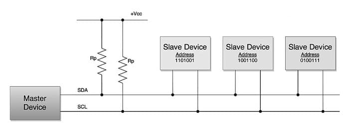
The I2C communication protocol operates using only 2 bi-directional open-drain lines for data transmission, known as SDA and SCL. Both of these lines are initially pulled high.
- Serial Data (SDA) : Data is transferred through this pin.
- Serial Clock (SCL): This pin carries the clock signal.
I2C operates in 2 modes –
- Master mode
- Slave mode
Every data bit transferred on the SDA line is synchronized by a transition from the high to low pulse of each clock signal on the SCL line.
As per the I2C protocols, the data line cannot change while the clock line is high;
It can only change when the clock line is low.
Since the devices on the I2C bus are actively low, pull-up resistors are required to keep lines high.
Data is transmitted in the form of packets consisting of 9 bits. The sequence of these bits includes:
- Start Condition: 1 bit
- Slave Address: 8 bits
- Acknowledge: 1 bit
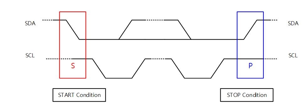
Start and stop conditions
I2C protocols are generated by keeping the SCL line high and changing the level of SDA.
To generate a start condition, the SDA line is transitioned from high to low while keeping SCL high.
Conversely, to generate a stop condition, the SDA line transitions from low to high while keeping the SCL high.
A high Read/Write bit indicates that the master is sending the data to the slave, whereas a low Read/Write bit indicates that the master is receiving data from the slave.
Designing the Board
For the Master board , I'll be using the board developed during the electronics design week . This board features a push button. Additionally, it has the necessary I2C pins required for communication.
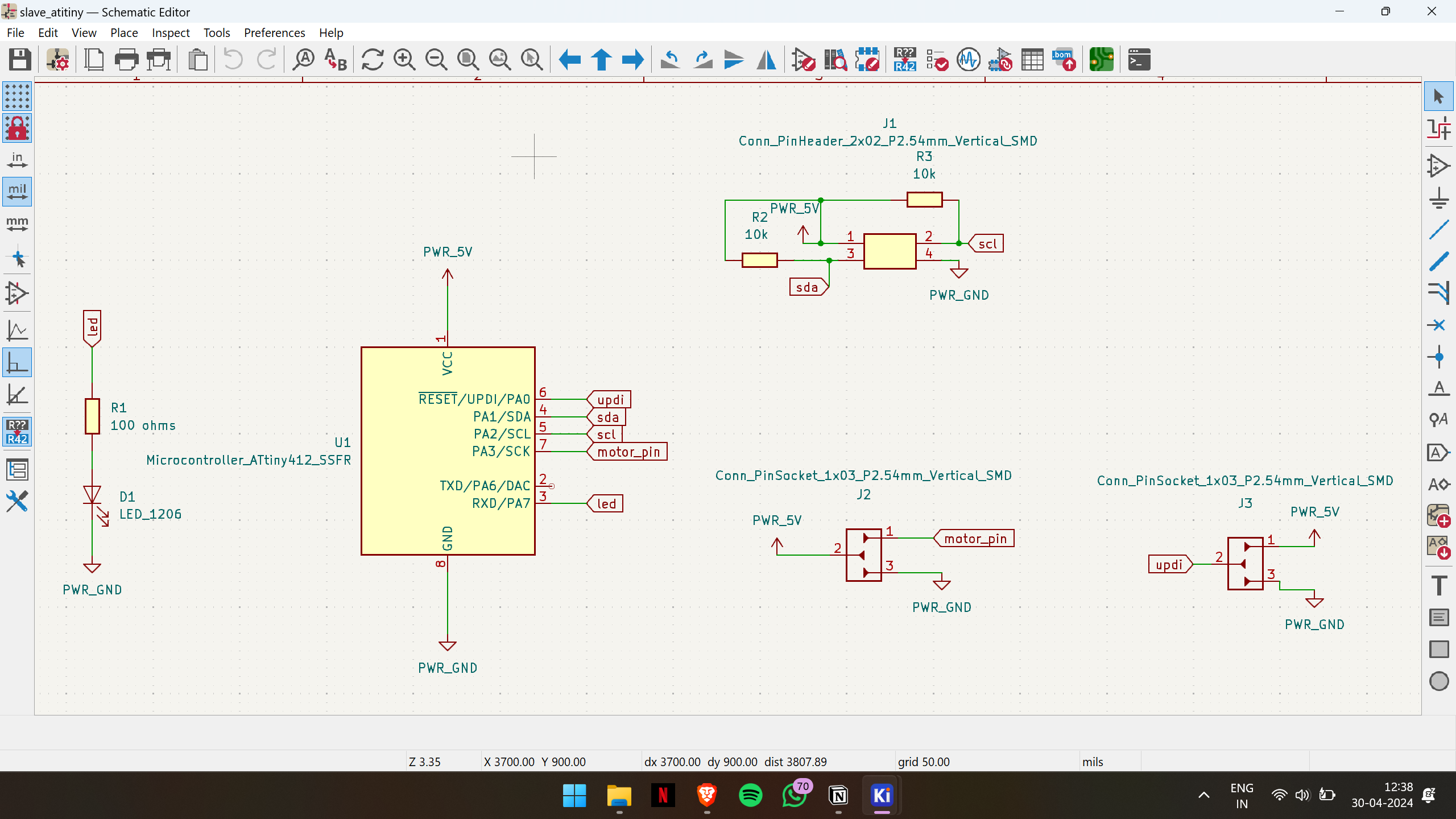
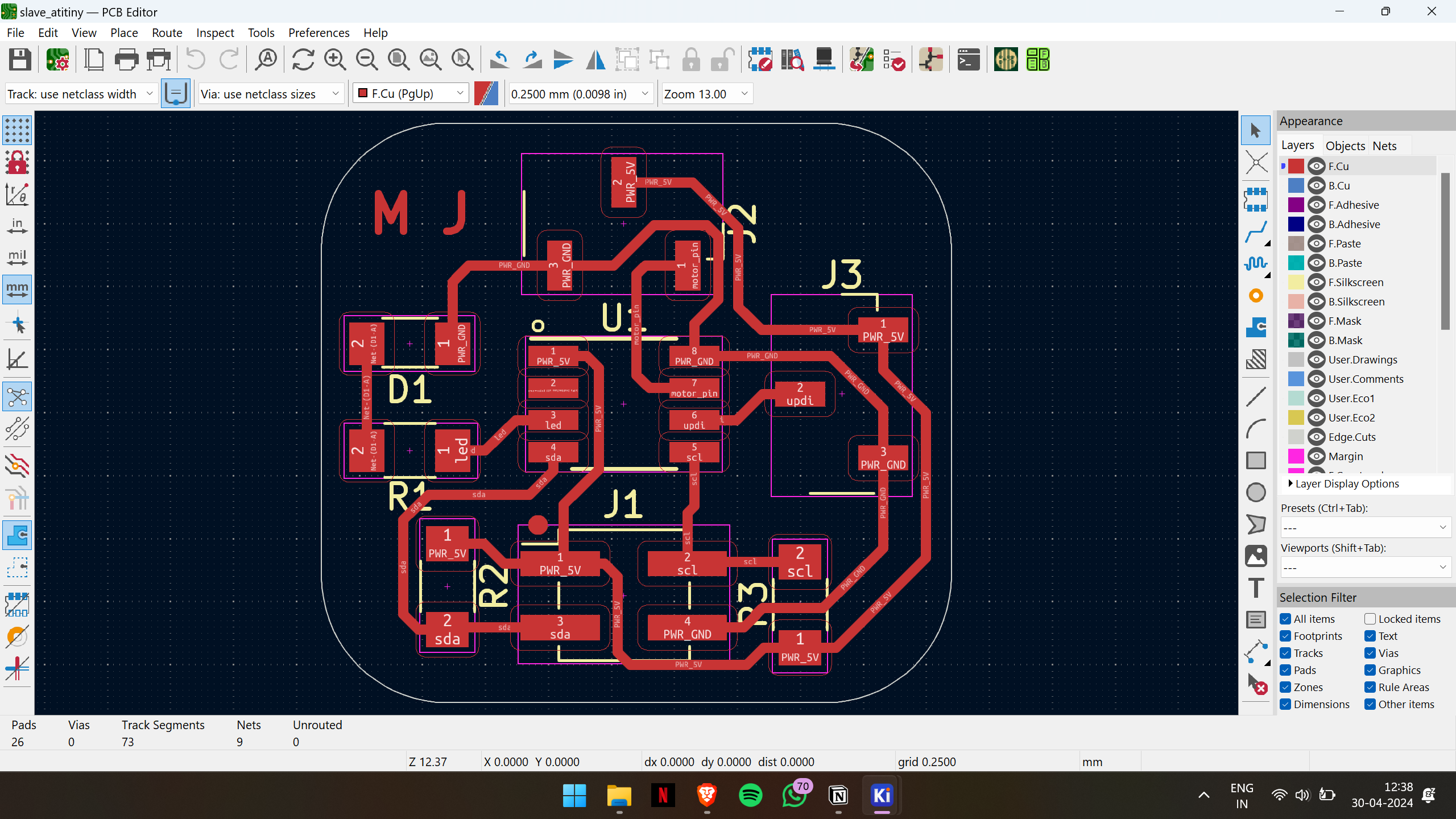
For the Slave board , I'll be designing a new board. I'll use the ATtiny412 microcontroller, which includes an LED and the necessary pinouts for I2C communication. Additionally, I'll ensure it supports burning the bootloader.
Here is the schematic diagram of the board
Here is the PCB layout
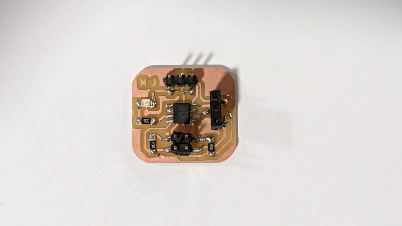
After obtaining the design file, I proceeded with the milling process.
After milling the board, I soldered the components in place. Here is the output.
Then, I replicated the same board design for the next slave.
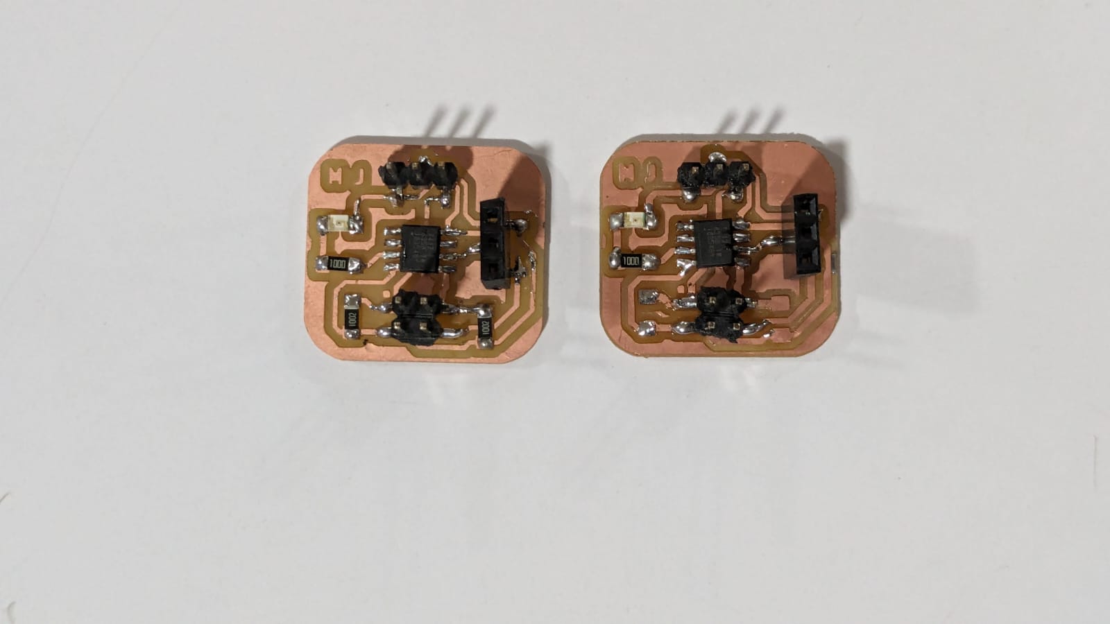
To test the functionality of the slave boards, I uploaded the basic Blink example sketch from Arduino. Both boards are working fine.
Unfortunately, I forgot to record a video of the testing phase.
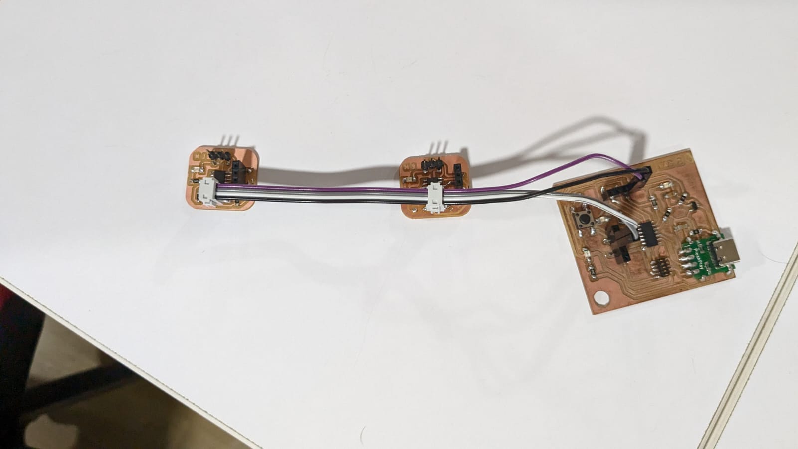
Next , I connected the master board with the slaves and began working on the software side of the project.
Code for master board
here is the prompt that i have given to generate this code using Chat GPT
Write an Arduino sketch that:
- Toggles LEDs on two I2C slave devices using a push button.
- The button is connected to pin 9.
- Alternates between two slave devices with addresses 8 and 9.
- Sends a command to toggle the LEDs on these devices.
- Uses a counter to keep track of button presses.
- Includes debouncing for the button to ensure stable readings.
#include <Wire.h>

const int buttonPin = 9;
int counter = 0;

void setup() {
  pinMode(buttonPin, INPUT_PULLUP);
  Wire.begin();
}

void loop() {
  int buttonState = digitalRead(buttonPin);


  if (buttonState == LOW) {
    counter++;


    int slaveAddress = (counter % 2 == 0) ? 8 : 9;
    int ledState = (counter % 2 == 0) ? 0 : 1;

    // Send command to toggle LED on the selected slave device
    Wire.beginTransmission(slaveAddress);
    Wire.write(ledState);
    Wire.endTransmission();

    delay(500);
  }

  delay(100);
}
Explanation of the above code
Include the Wire Library
#include <Wire.h>- This line includes the Wire library, which provides the necessary functions to communicate using the I2C protocol.
Define Constants and Variables
const int buttonPin = 9; // Pin connected to the push button
int counter = 0; // Counter to alternate between slave devices-
buttonPinis a constant integer that holds the pin number to which the push button is connected.
-
counteris an integer variable used to keep track of the number of button presses, helping alternate between slave devices.
Setup Function
void setup()
{
  pinMode(buttonPin, INPUT_PULLUP); // Set the button pin as an input with internal pull-up resistor
  Wire.begin();                     // Join I2C bus
}
-
pinMode(buttonPin, INPUT_PULLUP);configures thebuttonPinas an input and enables the internal pull-up resistor to keep the pin at a high logic level when the button is not pressed.
-
Wire.begin();initializes the I2C communication as a master device.
Loop Function
void loop() {
int buttonState = digitalRead(buttonPin); // Read the state of the button-
buttonStatereads the current state of the button. It will beHIGHwhen the button is not pressed (due to the pull-up resistor) andLOWwhen the button is pressed.
  // If the button is pressed, toggle the LEDs on the slave devices
  if (buttonState == LOW) {
counter++; // Increment counter-
If the button is pressed (
buttonState == LOW), increment thecounter.
    // Determine which slave device to toggle based on the counter value
    int slaveAddress = (counter % 2 == 0) ? 8 : 9;
int ledState = (counter % 2 == 0) ? 0 : 1;-
slaveAddressis set to 8 if thecounteris even and 9 if thecounteris odd. This alternates the target slave device between two addresses.
-
ledStateis set to 0 if thecounteris even and 1 if thecounteris odd. This toggles the LED state to be sent to the slave device.
    // Send command to toggle LED on the selected slave device
    Wire.beginTransmission(slaveAddress); // Start communication with the selected slave device
    Wire.write(ledState); // Send command to toggle LED based on the current LED state
Wire.endTransmission(); // End communication-
Wire.beginTransmission(slaveAddress);starts I2C communication with the slave device at the specified address.
-
Wire.write(ledState);sends theledStatevalue (0 or 1) to the slave device.
-
Wire.endTransmission();ends the I2C communication.
    delay(500); // Delay to debounce the button
  }

  delay(100); // Small delay between readings for stability
}-
delay(500);introduces a delay of 500 milliseconds to debounce the button, preventing multiple counts from a single press.
-
delay(100);adds a small delay of 100 milliseconds between loop iterations to stabilize the readings.
Code for slave board
here is the prompt that i have given to generate this code using Chat GPT
-
Write an Arduino sketch that:
- Acts as an I2C slave device.
- Controls an LED connected to pin 13.
- Uses I2C address 8 (with an option to change to address 9).
- Initializes the LED to a low state.
- Registers a function to handle incoming data from the I2C master.
-
Reads commands from the I2C master in the registered function:
- If the command is 0, turns off the LED.
- If the command is 1, turns on the LED.
- Updates the LED state based on the received command.
- Keeps the main loop empty, except for a small delay for stability.
#include <Wire.h>

const int ledPin = 13;
int ledState = LOW;

void setup() {
  pinMode(ledPin, OUTPUT);
  digitalWrite(ledPin, ledState);

  Wire.begin(8);
  // Wire.begin(9); // Uncomment this and comment the above line for the second slave with address #9
  Wire.onReceive(receiveEvent);
}

void loop() {

  delay(100); // Small delay for stability
}

// Function to handle incoming data from the master
void receiveEvent(int howMany) {
  while (Wire.available()) {
    int command = Wire.read();
    if (command == 0) {
      ledState = LOW;
    } else if (command == 1) {
      ledState = HIGH;
    }
    digitalWrite(ledPin, ledState);
  }
}
Explanation of the above code
Include the Wire Library
#include <Wire.h>- This line includes the Wire library, which provides the necessary functions to communicate using the I2C protocol.
Define Constants and Variables
const int ledPin = 13; // Pin connected to the LED
int ledState = LOW; // Variable to hold the current LED state-
ledPinis a constant integer that holds the pin number to which the LED is connected.
-
ledStateis an integer variable used to keep track of the current state of the LED (LOWfor off,HIGHfor on).
Setup Function
void setup() {
  pinMode(ledPin, OUTPUT); // Set the LED pin as an output
digitalWrite(ledPin, ledState); // Initialize the LED to the initial state-
pinMode(ledPin, OUTPUT);sets theledPinas an output pin so it can drive the LED.
-
digitalWrite(ledPin, ledState);initializes the LED state based on the initial value ofledState(which isLOW, so the LED will be off).
  Wire.begin(8); // Join I2C bus with address #8 for the first slave
  // Wire.begin(9); // Uncomment this and comment the above line for the second slave with address #9
Wire.onReceive(receiveEvent); // Register the receive even-
Wire.begin(8);initializes the I2C communication and sets the device address to 8. This means the device will respond to I2C communication directed to address 8.
-
The commented line
// Wire.begin(9);is an alternative initialization for a device with address 9. Uncomment this line and comment the previousWire.begin(8);line to switch the address.
-
Wire.onReceive(receiveEvent);registers thereceiveEventfunction as the event handler to be called whenever data is received via I2C.
Loop Function
void loop() {
  // Main loop does nothing, all the work is done in the receiveEvent function
  delay(100); // Small delay for stability
-
The
loopfunction is intentionally left almost empty because the actual work is done in thereceiveEventfunction. Thedelay(100);introduces a small delay for stability, ensuring the loop doesn't run too fast.
Receive Event Function
// Function to handle incoming data from the master
void receiveEvent(int howMany) {
  while (Wire.available()) {
    int command = Wire.read(); // Read the command from the master
    if (command == 0) {
      ledState = LOW; // Turn off the LED
    } else if (command == 1) {
      ledState = HIGH; // Turn on the LED
    }
    digitalWrite(ledPin, ledState); // Update the LED state
  }
}-
receiveEvent(int howMany)is the event handler function that gets called whenever data is received from the I2C master.
-
Inside this function, a
while (Wire.available())loop runs as long as there is data available to read.
-
int command = Wire.read();reads a byte of data (the command) sent by the master device.
-
The
ifstatement checks the value ofcommand:-
If
command == 0, it setsledStatetoLOW, turning off the LED.
-
If
command == 1, it setsledStatetoHIGH, turning on the LED.
-
If
-
digitalWrite(ledPin, ledState);updates the actual state of the LED to matchledState.
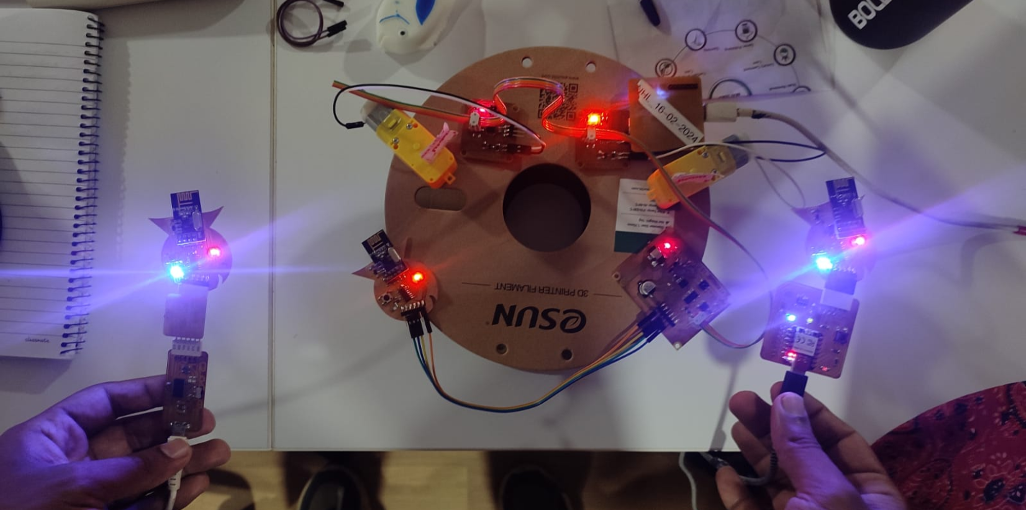
Here is the output I achieved.
Group assignment: click here
Send a message between two projects